Design and Development of IC Card Cable Charge Controller
With the deep promotion of IC card wired application technology, the modernization level of property management has been continuously improved, and the IC card cable TV charging system has emerged. The emergence of IC card cable TV charging system has solved the problem that the cable TV industry has difficulty in charging and management in the past, and it also makes the user charging method more convenient and flexible. We designed the IC card cable TV charging system, which is mainly composed of a computer network management software system and a user cable TV charging controller. This article mainly introduces the design of the user cable TV charging controller.
1 IC card cable TV charging controller mode
When the user inserts the fee-containing IC card (stored in date form) into the charging controller, the bistable video signal controller turns on the video signal, and the user can normally view it. When the payment date arrives, the charging controller bistable video signal controller disconnects the video channel, and the user must re-pay the card. The IC card with the fee will be inserted into the charging controller again before continuing to view. Under normal circumstances, the bistable video signal controller is in the on state, and the user normally views. The on/off state of the bistable video signal controller is affected only when a special event occurs. As shown in Figure 1.
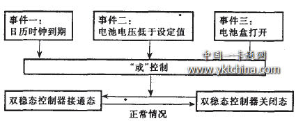
figure 1
2 IC card cable TV charging controller composition and function
The IC card cable charging controller consists of a low-power single-chip microcomputer, a bistable video signal controller, a serial calendar clock, a nonvolatile memory, a liquid crystal display, a power supply voltage detector, and a battery pack (see FIG. 2). Among them, the IC card adopts the 88SC 102 encryption card, which is characterized by large capacity and good security.
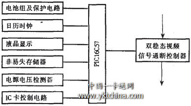
Figure 2 IC card cable TV charging controller
2.1 Low Power Microcontroller PIC 16C57
The PIC 16C57 microcontroller features low cost, high performance, low power consumption, and easy programming. When it is in sleep state, the state power consumption is <=1 μA.
The PIC 16C57 MCU can realize the operation of the IC card reader through the IC card control circuit. At the same time, the useful information in the card can be stored in the non-volatile memory after being identified and processed, and the calendar clock and the battery voltage are detected periodically. Information is displayed on the liquid crystal through the controller interface. The output port of the MCU is connected to the driving circuit to realize the on-off control of the bistable video signal controller.
2.2 bistable video signal controller switch
At present, relays or high-frequency electronic switches are commonly used for on-off control of video signals. When the relay is in working state, it needs a large holding current, and is also susceptible to changes in the on and off states due to electrical interference, mechanical shock and vibration. Generally, high-frequency electronic switches, whether using discrete components or integrated chips, will be used for cable television signals. Different degrees of interference or attenuation are generated, and it is difficult to effectively turn off the signal in the UHF band.
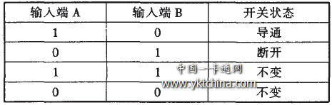
In response to the above problems, we have developed a control method consisting of a DC micromotor and a specific mechanical structure, which can ideally achieve reliable turn-on and turn-off of cable television signals. In the on and off states, there is no power consumption, and the on and off states are very stable. Except for the on/off control signals, other electrical disturbances, mechanical shocks, and vibrations cannot change their on and off states. The cable television signal control device implemented by the method can realize high-fidelity transmission of the cable television signal when turned on, and can be reliably turned off when turned off. Table 1 shows the control logic table, where A and B are the two electrical signal input terminals of the controller.
2.3 serial calendar clock
IC card cable TV charging device calendar clock uses trickle charge DS1302 chip, its application circuit structure diagram shown in Figure 3. Among them, the MCU line RB7, RB6, RBS respectively
DS13 02 RST, I / 0 and SCLK are connected, Vcc2 is connected to the main power supply, Vcc I is connected to the 3V backup battery. To prevent the backup battery from dropping power, turn on the trickle charger to charge the spare battery. When the main power supply voltage drops or is powered off, it automatically switches to the backup battery.
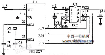
Figure 3 IC card cable TV charging controller circuit structure diagram
In the process of debugging the calendar module, pay attention to the following issues:
(1) Control port line In the DS13 02, three control port lines RST, SCLK, I/O are respectively connected with a 40k pull-down resistor to ensure that RST is low when power is on. Please note that when the data is input/output, the I/0 pin is tri-stated on the rising edge of SCLK.
(2) Crystal Oscillator The crystal oscillator is available in KDS7D specification and is 32.768kHz. The crystal oscillator is directly connected to the DS 1302. No external components are required. It is best not to be at both ends of the oscillator and to the ground to avoid affecting the timing accuracy. If there is a precision error, a capacitor of about 6μF can be used across the oscillator. It should be specially reminded that due to the weak oscillating signal, it is difficult to observe the oscillation waveform of the crystal oscillator with an ordinary oscilloscope.
(3) Initialization register There are 7 registers related to the calendar and clock, and the stored data is in the form of BCD code. The seventh bit of the second register is the clock pause bit. When this bit is set to 1, the clock oscillator stops, and the DS 1302 enters the low power standby state. When set to 0, the clock oscillator operates. The initial value is defined for all 7 registers (80h, 82h, ---, 8ch) during initialization. Otherwise, the DS1302 will be in the low power standby state. If trickle charge is used, the trickle charger register (90h) can be defined as b7h, that is, a diode string 8k resistor is used to charge the backup power supply. The maximum fine charging current is:
Imax = ( 5 V - 0.7 V ) / 8 K = 0 .54 mA. To prevent any other register mis-writing operations, bit 7 of the control register (8Eh) can be defined as write-protected (ie, this bit is set to 1).
2.4 Data Nonvolatile Memory Circuit
The non-volatile memory uses the 24LC01 chip, which can be used to store important data in the system for long-term reliability. After the user card is inserted into the system, key data such as the card password and card number will be stored in the memory 24LC01 in the form of cipher text through the single chip microcomputer. When the user uses it, the dynamic data will also be accurately recorded in the memory 24LC01 at any time.
2.5 Buck monitoring circuit
The step-down monitoring adopts S80751. When the system battery voltage is at a normal value, the output pin 1 of the voltage monitoring chip 580751 is high. When the system battery voltage is lower than 5.1V, the output pin 1 of the voltage monitoring chip 580751 becomes low. After the MCU detects a low level, it will control the LCD display undervoltage to remind the user to replace the battery.
2.6 Battery box open state monitoring circuit
When the battery case is closed, the output of the protection circuit is high; when the battery case is pulled open, the protection circuit input terminal is low. After the MCU monitors the low level, the video signal is cut off until the battery is installed and the battery box is pushed into the watch. After the output of the protection circuit is turned high again, the MCU will re-connect the video signal.
2.7 LCD and sound and light alarm circuit
The liquid crystal is made by PHILIP standard 12C communication module, which can display four kinds of information states of undervoltage, arrears, video signal cutoff and card error, and any combination thereof. The sound and light alarm circuit adopts high-brightness LED and high-buzzer buzzer, and the sound and light alarm is controlled by the single-chip microcomputer.
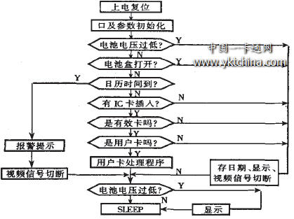
3 software main flow chart
The software uses the PIC 16C5X block diagram shown in Figure 4.
About the Author:
Hefei Institute of Intelligent Machinery, Chinese Academy of Sciences Xing Wu, Chen Jialin, Long Fei, Li Feng, Yao Yubao, Tang Bing
ã€references】
DS1302T rickleC hargeT imekeepingC hip.D ALLASS emiconductor Corpomtion, 1999
Cai Chunjie, Xing Wu. The principle and application of PIC16/17 single chip microcomputer. Hefei: University of Science and Technology of China Press, 1997
Yuanfu offers this stunning new product with a modern stylish design, the Bathroom Range. This unit is a simple yet elegant piece of Bathroom Furniture, with its tong and grove effect panelling having the ability to enhance any bathroom. This free standing unit features a smooth white finish, cut out design handles and ample storage space. Lastly, this unit is traditional yet modern and will suit all decors.Keep your bathroom essentials neatly stored away in this Mirrored Tall Cabinet. With the external shelves, you'll have plenty of space for your toiletries and you can even keep some things out of site, in 4 internal shelves. Finished in a clean white with rounded metal handles, you'll add a touch of sophistication to your bathroom.
Bathroom Cabinet,Bathroom Storage Cabinet,Bathroom Sink Cabinets,Corner Bathroom Cabinet
FuJian YuanFu Import&Export Trading Co., Ltd. , https://www.fjyffurniture.com